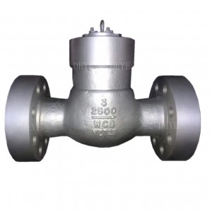
A216 WCB 900LBS Check Valve
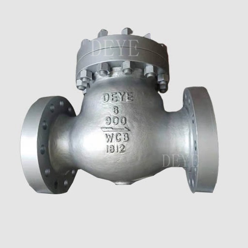


carbon steel 900LBS flanged swing Check Valve
Design standard: API 600.API594 BS1868
Body material: WCB. Carbon Steel
Nominal diameter: 6”DN150
Pressure: CL900LBS
End connection: RF. Flange
Face to face: ASME B16.10.
Working temperature: -29℃~+425℃.
Test and inspection: API 598.
Full bore Check valves
High Pin Flat Disc Check Valves
Integral Disc check valves
On Request
Available Material: A216WCB/WCC/LCB/WC9/C5/CF8M/CF3
Optional Stem: A182F6a, A182F304, A182F316, F51/F53
Optional Seat & Trim: STL, 2CR13, SS304, SS316/F51
Optional End connection:
Range of valve sizes diameter: 1/2″~60″ (DN15~DN1500).
Range of pressure: 150lbs~2500lbs (PN16~PN420).
Optional: By pass design
Optional Operation: automatic type or Lever and counter weight
Performance:
INSPECTION BEFORE INSTALLATION
- Before installation, check the valve name plate and valve body information to ensure the valve is suitable for the intended service.
- Before installation, remove the flange cover and the protective film on the flange sealing face, and disc support, inspect the bore and the flange sealing surface, remove any dirt with clean soft cloth, use an anti-corrosive cleaning liquid to clean if necessary, and never use any other chemical products.
- Inspect the flange gasket (including ring gasket) sealing surface and ensure it is in acceptable condition for installation. Install Position the valve into the pipe or the flange connection; ensure that any stress caused by improper pipe alignment is relieved first. Valves are not intended to be a means of aligning improperly fitted pipe.2 Valves marked with flow direction must be installed in line with the piping flow.3 Valve should be installed in a horizontal position with the center of the valve.
Application:
The medium is water, steam, gas, corrosive medium, oil, medicine, etc.
Available Material: A216WCB/WCC/LCB/WC9/C5/CF8M/CF3
Optional Stem: A182F6a, A182F304, A182F316, F51/F53
Optional Seat & Trim: STL, 2CR13, SS304, SS316/F51
Optional End connection:
Range of valve sizes diameter: 1/2″~60″ (DN15~DN1500).
Range of pressure: 150lbs~2500lbs (PN16~PN420).
Optional: By pass design
Optional Operation: automatic type or Lever and counter weight
INSPECTION BEFORE INSTALLATION
Before installation, check the valve name plate and valve body information to ensure the valve is suitable for the intended service.
Before installation, remove the flange cover and the protective film on the flange sealing face, and disc support, inspect the bore and the flange sealing surface, remove any dirt with clean soft cloth, use an anti-corrosive cleaning liquid to clean if necessary, and never use any other chemical products.
Inspect the flange gasket (including ring gasket) sealing surface and ensure it is in acceptable condition for installation.
INSTALLATION
1 Position the valve into the pipe or the flange connection; ensure that any stress caused by improper pipe alignment is relieved first. Valves are not intended to be a means of aligning improperly fitted pipe.
2 Valves marked with flow direction must be installed in line with the piping flow.
3 Valve should be installed in a horizontal position with the center of the valve.
The medium is water, steam, gas, corrosive medium, oil, medicine, etc.