Carbon steel PN25 Safety valve (SV-150-2×3)
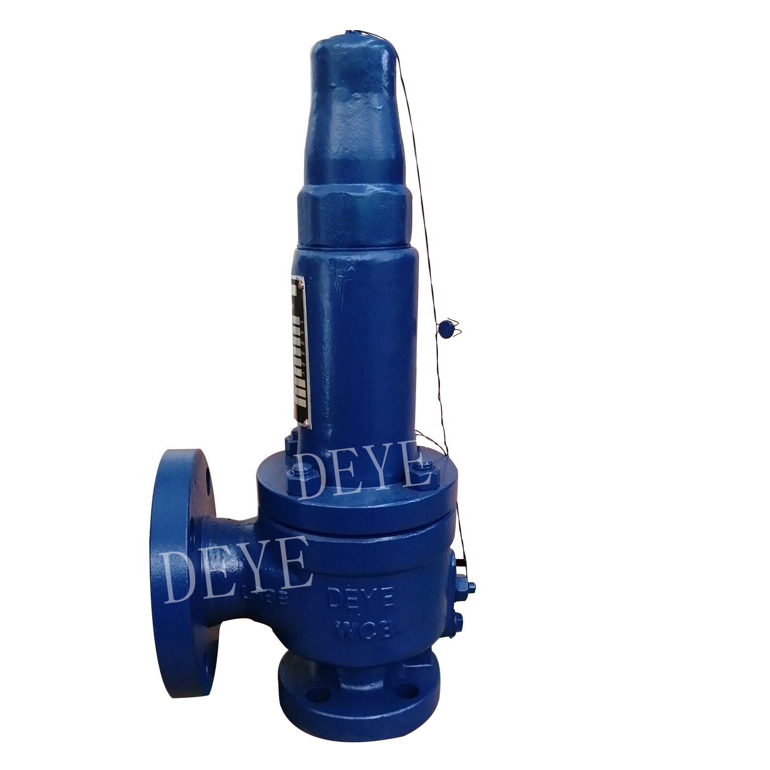


Quick details:carbon steel flanged PN25 pressure relief valve
PRESSURE SAFETY VALVE 150#
Safety relief, Close bonnet, Full nozzle, Bolted cap
Fluid state: liquid
Body and bonnet: ASME SA 216 Gr. WCB CS
Disc and Seat:304
Resilient seat seal: Viton
Guide and rings:SS316
Spring:50CrVA
Nozzle: 304
Percent overpressure:10%
Valve discharge coefficient:0.65
Sizing basis: Blocked discharge
Product Range:
Sizes: 1/2″ x 1″, 3/4″ x 1.1/4″, 1″ x 1.1/2″, 1.1/4″ x 2″, 1.1/2″ x 2.1/2″, 2″ x 3″, 2.1/2″ x 4″
Connections: Flanged DIN or ANSI
Materials: Carbon Steel or Stainless Steel
Disk MaterialMetal, Viton, Nylon, PEEK
Joints & Seals: NBR, FPM, EPDM (depending upon model)
Medium: Steam, Gases and Liquids
Set Pressure: 0.1 to 220 Barg (depending upon size)
Temperature: (32.1) -10 to 280 degC, (32.2) -60 to 280 degC, (32.7) -200 to 280 degC
Performance
safety valve used to control or limit the pressure in a system; pressure might otherwise build up and create a process upset, instrument or equipment failure, or fire. The pressure is relieved by allowing the pressurized fluid to flow from an auxiliary passage out of the system. The relief valve is designed or set to open at a predetermined set pressure to protect pressure vessels and other equipment from being subjected to pressures that exceed their design limits. When the set pressure is exceeded, the relief valve becomes the “path of least resistance” as the valve is forced open and a portion of the fluid is diverted through the auxiliary route. The diverted fluid (liquid, gas or liquid–gas mixture) is usually routed through a piping system known as a flare header or relief header to a central, elevated gas flare where it is usually burned and the resulting combustion gases are released to the atmosphere. As the fluid is diverted, the pressure inside the vessel will stop rising. Once it reaches the valve’s reseating pressure, the valve will close. The blowdown is usually stated as a percentage of set pressure and refers to how much the pressure needs to drop before the valve reseats. The blowdown can vary from roughly 2–20%, and some valves have adjustable blowdowns.
Application:
Used in equipment and pipelines with oil, air, water and other media with working temperature ≤300℃.
.
Sizes: 1/2″ x 1″, 3/4″ x 1.1/4″, 1″ x 1.1/2″, 1.1/4″ x 2″, 1.1/2″ x 2.1/2″, 2″ x 3″, 2.1/2″ x 4″
Connections: Flanged DIN or ANSI
Materials: Carbon Steel or Stainless Steel
Disk MaterialMetal, Viton, Nylon, PEEK
Joints & Seals: NBR, FPM, EPDM (depending upon model)
Medium: Steam, Gases and Liquids
Set Pressure: 0.1 to 220 Barg (depending upon size)
Temperature: (32.1) -10 to 280 degC, (32.2) -60 to 280 degC, (32.7) -200 to 280 degC
safety valve used to control or limit the pressure in a system; pressure might otherwise build up and create a process upset, instrument or equipment failure, or fire. The pressure is relieved by allowing the pressurized fluid to flow from an auxiliary passage out of the system. The relief valve is designed or set to open at a predetermined set pressure to protect pressure vessels and other equipment from being subjected to pressures that exceed their design limits. When the set pressure is exceeded, the relief valve becomes the “path of least resistance” as the valve is forced open and a portion of the fluid is diverted through the auxiliary route. The diverted fluid (liquid, gas or liquid–gas mixture) is usually routed through a piping system known as a flare header or relief header to a central, elevated gas flare where it is usually burned and the resulting combustion gases are released to the atmosphere. As the fluid is diverted, the pressure inside the vessel will stop rising. Once it reaches the valve’s reseating pressure, the valve will close. The blowdown is usually stated as a percentage of set pressure and refers to how much the pressure needs to drop before the valve reseats. The blowdown can vary from roughly 2–20%, and some valves have adjustable blowdowns.
Used in equipment and pipelines with oil, air, water and other media with working temperature ≤300℃.